Rtl Code For Full Adder / Full Adder Implementation Using Vhdl On Basys 3 And 2 Fpga Board / S= a (exor) b c=a.b
Get link
Facebook
X
Pinterest
Email
Other Apps
Rtl Code For Full Adder / Full Adder Implementation Using Vhdl On Basys 3 And 2 Fpga Board / S= a (exor) b c=a.b. As we know , in ripple carry adder , we need full adder so during code writing we also use the full adder code so make sure you made a full adder before making ripple carry adder. In_x = 0, in_y = 0, carry_in = 0, out_sum_fa = 0, out_carry_fa = 0 In this post, we will take a look at implementing the vhdl code for full adder using structural architecture. Half adders are a basic building block for new digital designers. Slideshare uses cookies to improve functionality and performance, and to provide you with relevant advertising.
In the second pass of the design, we are going to build the circuit using the ieee std_logic unsigned package, a much more code efficient and scalable design. Verilog and system verilog are programming languages designed to code hardware at register transfer level. If not then here is some basic on full adder what it is and why we need it, if yes… A synchronous digital circuit is modeled with following considerations: Yes, obviously sum is supposed to be connected to the module which requires the sum of a and b.
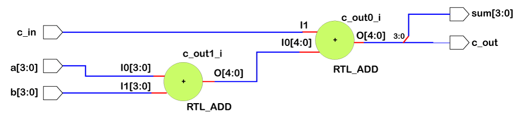
Vhdl Code For Full Adder Supernalcb from supernalcb.weebly.com It is the main component inside an alu of a processor and is used to increment addresses, table indices, buffer pointers, and other places where addition is required. Verilog and system verilog are programming languages designed to code hardware at register transfer level. A synchronous digital circuit is modeled with following considerations: Rtl analysis, synthesis, implementation and program and debug. Cout is high, when two or more inputs are high. If not then here is some basic on full adder what it is and why we need it, if yes… Slideshare uses cookies to improve functionality and performance, and to provide you with relevant advertising. Rtl schematic for full adder circuit testbench for full adder in verilog.
Cout is high, when two or more inputs are high.
Now, click on run synthesis, 2 nd option in synthesis. In this notation, the first bit is used to denote the sign of the… Vhdl code of half adder using the dataflow model.it contains vhdl code for rtl diagram, simulation code and the waveform half adder. Vhdl code for full adder will be given in later part of this article. Full adder trial layout in figure1 is reported a trial layout on altera quartus ii using a cyclone v fpga. Signed numberssigned magnitude adderverilog code for signed adderrtl viewtesting circuit for signed adderstimulation 1. Half adderfull adderverilog code rtl viewstimulation half adder if you are reading this blog, then you are probably familiar with digital electronics. Verilog full adder in dataflow & gate level modelling style. It is the main component inside an alu of a processor and is used to increment addresses, table indices, buffer pointers, and other places where addition is required. If not then here is some basic on full adder what it is and why we need it, if yes… As is customary in our vhdl course, first, we will take a look at the logic circuit of the full adder.since we are using the structural method, we need to understand all the elements of the hardware. The digital hardware consists of concurrent and sequential events. // fpga4student.com // fpga projects, vhdl projects, verilog projects // verilog code for full adder // structural code for full adder module full_adder_structural_verilog( input x1, x2, cin, output s, cout );
The red text ties into the code below. In_x = 0, in_y = 0, carry_in = 0, out_sum_fa = 0, out_carry_fa = 0 It starts with a grave accent ` and does not end with a semicolon. The rtl codes are developed for full adder using both the designs. Here given fig.1 is one bit half adder in the lowest level of the abstration diagram is there as similarly we know their are two ways to designed one bit full adder either using two half adder and one or gate or designed using their separate boolean expression as shown in below fig.2 and fig.3.
Vhdl Code For Full Adder Supernalcb from supernalcb.weebly.com Signed numberssigned magnitude adderverilog code for signed adderrtl viewtesting circuit for signed adderstimulation 1. The verilog codes are then simulated using the cadence nc sim and the waveform obtained on the graphical user interface is used to verify the operation of the adder incorporating the aforementioned optimization technique. Signed adder using verilog concepts to be covered: To understand the operation of a full adder, logic equation and the truth table; Let us look at the source code for the implemmentation of a full adder fulladder.v /* full adder module for bit addition. First, vhdl code for half adder was written and block was generated. Half adderfull adderverilog code rtl viewstimulation half adder if you are reading this blog, then you are probably familiar with digital electronics. In this video we teach how to code for full adder in verilogmusic:
Full adder trial layout in figure1 is reported a trial layout on altera quartus ii using a cyclone v fpga.
Vhdl code of half adder using the dataflow model.it contains vhdl code for rtl diagram, simulation code and the waveform half adder. Half adderfull adderverilog code rtl viewstimulation half adder if you are reading this blog, then you are probably familiar with digital electronics. Concepts covered in the blog : We'll first add the timescale directive. It starts with a grave accent ` and does not end with a semicolon. The sum s and the carry out c_out, where s=a^b^c_in, and c_out=ab+bc+ac, where ^ the xor logic operation and + is the logic or operation. Cout is high, when two or more inputs are high. Yes, obviously sum is supposed to be connected to the module which requires the sum of a and b. Here or use the structural verilog code for the full adder based on its logic diagram as follows: Once the functionality of the circuit is verified. Slideshare uses cookies to improve functionality and performance, and to provide you with relevant advertising. Sum (s) output is high when odd number of inputs are high. If you continue browsing the site, you agree to the use of cookies on this website.
Rtl schematic for full adder circuit testbench for full adder in verilog. If not then here is some basic on full adder what it is and why we need it, if yes… Timescale directive is used for specifying the unit of time used in further modules and the time resolution (here one picosecond). To understand the operation of a full adder, logic equation and the truth table; Full adder trial layout in figure1 is reported a trial layout on altera quartus ii using a cyclone v fpga.
Verilog Full Adder Javatpoint from static.javatpoint.com The sum s and the carry out c_out, where s=a^b^c_in, and c_out=ab+bc+ac, where ^ the xor logic operation and + is the logic or operation. Half adders are a basic building block for new digital designers. This page of verilog sourcecode covers hdl code for half adder, half substractor, full substractor using verilog. To understand the operation of a full adder, logic equation and the truth table; Vhdl code of half adder using the dataflow model.it contains vhdl code for rtl diagram, simulation code and the waveform half adder. Design and implement a 4 bit full adder. Let us look at the source code for the implemmentation of a full adder fulladder.v /* full adder module for bit addition. Slideshare uses cookies to improve functionality and performance, and to provide you with relevant advertising.
Slideshare uses cookies to improve functionality and performance, and to provide you with relevant advertising.
The red text ties into the code below. The signed full adder vhdl code presented above is pure vhdl rtl code so you can use it independently on every kind of fpga or asic. The next picture shows the entire schematic of the full adder and its corresponding truth table. We'll first add the timescale directive. Slideshare uses cookies to improve functionality and performance, and to provide you with relevant advertising. First, vhdl code for half adder was written and block was generated. Half adders are a basic building block for new digital designers. Design and implement a 4 bit full adder. // fpga4student.com // fpga projects, vhdl projects, verilog projects // verilog code for full adder // structural code for full adder module full_adder_structural_verilog( input x1, x2, cin, output s, cout ); If not then here is some basic on full adder what it is and why we need it, if yes… To understand the operation of a full adder, logic equation and the truth table; Vhdl code for full adder will be given in later part of this article. Half adder module in vhdl and verilog.
Half adderfull adderverilog code rtl viewstimulation half adder if you are reading this blog, then you are probably familiar with digital electronics rtl code. The next picture shows the entire schematic of the full adder and its corresponding truth table.


Comments
Post a Comment